Inside Audio

Workflow

Interesting information that makes my work day just a little better.

  • Posted on
    Choosing the Right USB Isolator and Managing Digital Noise

    Choosing the Right USB Isolator and Managing Digital Noise

    When shopping specifically for an "audio-grade" device rather than one intended simply to protect computer ports or manage data flow, focus on these technical requirements:

    Galvanic Isolation Quality and Method
    Standard isolators often only provide basic protection against electrostatic discharge (ESD). An audio-grade unit must prioritize true galvanic isolation.

    • Optical/Optocoupler Coupling: Many high-end audio isolators use light to transmit data, which provides the most robust electrical separation between your computer's power plane and your sensitive analog gear. This is highly effective at eliminating "digital hash" caused by switching noise from a PC’s internal components.

    • Magnetic/Transformer Isolation: Some specialized units use high-speed transformers for isolation; these are also excellent but ensure they can handle the specific data throughput required without compromising signal integrity.

    Bandwidth and Protocol Support (Latency & Jitter)
    The biggest risk with "cheap" isolators is that they often limit you to older, slower protocols like USB 1.1 or limited versions of USB 2.0 High-Speed.

    • USB Speed Compliance: Ensure the device supports at least USB 2.0 (High-Speed) for basic audio interfaces, and ideally USB 3.x if you are running multi-channel high-sample rate workstations. A standard data isolator might slow down throughput significantly; an audio-grade one is engineered to maintain low latency essential for real-time monitoring.

    • Jitter Management: In digital audio, "jitter" (timing errors in the bitstream) can degrade sound quality or cause audible clicks/pops. Audio-grade hardware uses high-precision clocking mechanisms within its internal circuitry to ensure that the isolation process does not introduce temporal instability into your signal.

    Power Plane Separation and Regulation
    Standard data transfer isolators often focus on protecting against voltage spikes, but they may still allow significant "ripple" or noise from a computer's power supply to pass through via shared ground paths.

    • Independent Power Management: Look for an isolator that features its own dedicated regulated power input (often provided by a separate DC wall adapter) rather than drawing all its operating current directly and solely from the host USB bus. This ensures your audio interface isn't just inheriting the "dirty" electricity of a noisy computer motherboard through the isolation layer itself.

    High-Performance Interface Implementation
    Professional studios often solve digital interference by selecting interfaces specifically engineered with superior internal shielding and driver architecture to manage data bus transients effectively.

    • RME: Widely regarded for their highly optimized drivers and robust voltage regulation, which helps minimize jitter and the "digital hash" caused by computer power plane noise during real-time audio tasks.

    Power Supply Isolation (The Foundation)
    Because much of digital interference originates from a Computer's Switching Mode Power Supply (SMPS), professional isolation often occurs at the electrical source before it ever reaches your USB ports.

    • High-End Line Conditioners: Brands like Furman or IsoTek provide specialized filtering that suppresses EMI/RFI, preventing noise in a computer’s internal DC rails from being transmitted through high-speed data lines to an audio interface.

    External Power and Protocol Selection
    A common professional standard for achieving isolation is moving away from devices that rely on "Bus Powered" configurations (drawing power directly via the USB cable).

    • Dedicated External Power: Using interfaces with their own independent DC power supply provides a physical electrical separation between your computer’s noisy ground plane and your sensitive analog audio converters.

    • Thunderbolt Standards: In many high-end setups, Thunderbolt is preferred over standard USB because it offers better management of data throughput and signal timing (jitter), which reduces the likelihood of digital noise being introduced during heavy processing loads.

    👉 Return to RR.COM 👈

  • Posted on
    Practical Mitigation Strategies for USB Interface Noise

    Practical Mitigation Strategies for USB Interface Noise

    While digital noise can be difficult to track due to its high frequency and transient nature, several targeted solutions exist to ensure clean signal paths between your computer and audio hardware.

    High-Quality Powered Hubs
    Using a dedicated hub with external power provides an important layer of stability that the host's motherboard often cannot offer alone.

    • Decoupling Power: A powered hub delivers its own stable voltage source, decoupling your interface from the fluctuating current demands and electrical "noise" generated by other USB peripherals like mice or hard drives connected to a single computer controller.

    USB Galvanic Isolators
    For maximum signal integrity in sensitive environments, implement an isolator between the host and device.

    • Optical/Magnetic Separation: These devices use optocouplers (optical coupling) or specialized transformers to break direct electrical contact while allowing digital data to pass through via light pulses. This prevents high-frequency switching noise from a computer's power supply from ever entering your audio signal path.

    Balanced Signal Routing Post-Interface
    Protect the integrity of the analog stage once it leaves your interface by utilizing professional cabling standards.

    • Common-Mode Rejection: Always use balanced XLR or TRS connections for all downstream routing (from an interface to monitors, preamps, etc.). This ensures that any remaining EMI/RFI picked up along external cable runs is canceled out through common-mode rejection at the receiving device's input stage.

    Physical Cable Management and Separation
    Mitigate electromagnetic coupling by applying basic spatial principles used in all professional audio installations.

    • Spatial Decoupling: Keep USB data cables, balanced/unbalanced signal lines, and high-voltage power supplies physically separated to reduce the risk of interference being induced into your digital signals via proximity or induction.
  • Posted on
    Beyond Ground Lifts: When Isolation Transformers are Essential

    Beyond Ground Lifts: When Isolation Transformers are Essential

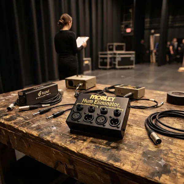
    While a ground lift switch is an excellent first line of defense for simple hum in microphone cables, it only works by breaking the electrical connection on Pin 1. This does not solve every noise problem encountered in professional environments. In many complex scenarios, you require Galvanic Isolation—a state where two circuits are completely electrically separated and communicate purely through magnetic induction via a transformer.

    Capacitive Coupling Interference This occurs when electromagnetic noise from another source "jumps" across an air gap or insulation between two conductors (like running power cables next to audio lines).
    - The Problem: A ground lift breaks physical continuity but does nothing to stop the magnetic/electrical field induction that passes through space into your cable shielding. - The Solution: An isolation transformer physically separates both signal and shield wires, using a primary and secondary winding so no electricity can actually jump between them via capacitance or proximity.

    High Potential Voltage Differentials in Large Racks
    In professional studios with multiple power circuits (e.g., one for lighting/dimmers and another for audio gear), there is often a significant "potential difference" between the electrical ground of two different pieces of equipment, even if they are both correctly grounded to their respective outlets. - The Problem: A simple switch might break your local loop, but high currents or noise can still travel through shared metal chassis/casing paths in complex interconnected hardware systems that aren't addressed by a single cable lift.
    - The Solution: An isolation transformer provides total electrical decoupling between the two pieces of gear, ensuring they are electrically "blind" to each other’s ground potential fluctuations and switching noise from power supplies.

    Line Level Complexity & Digital Gear Interfacing
    When connecting high-voltage line level equipment or digital interfaces (like a computer's audio output going into an external outboard processor), the signal paths become much more complex than simple microphone lines. - The Problem: Standard DI boxes are optimized for low voltage; attempting to use them on higher impedance/higher amplitude signals can lead to clipping and insufficient isolation of "digital buzz" caused by high-frequency switching power supplies in computers or digital converters.
    - The Solution: A dedicated line level isolator uses heavy-duty transformers designed specifically for these signal levels, providing the robust galvanic separation needed to keep computer noise out of expensive analog hardware processing chains.

    👉 Return to RR.COM 👈

  • Posted on
    Navigating AES on the Sound Devices 833

    Navigating AES on the Sound Devices 833

    Introduction: Why Go Digital?

    • The Benefit: AES (Audio Engineering Society) connections allow for a pure digital signal path from source (like a high-end digital wireless receiver or preamp) to the 833.

    • The Advantage: Avoiding unnecessary A-to-D (Analog-to-Digital) and D-to-A conversion stages, which can introduce noise or color the sound. (HEDD Audio)

    Identifying Your AES Entry Points

    There are two ways to get AES into an 833:

    • The "Native" Input: XLR Input 1 is capable of accepting AES3 or AES42 (for digital mics). This is perfect for a quick, single-source digital connection. (Broadcast Supply Worldwide)

    • The Expansion Method (XL-AES): For more serious channel counts, introduce the XL-AES accessory. It attaches directly to the top of the 833, providing four TA3 connectors, each capable of carrying two channels of AES, for a total of eight digital inputs. (Sound Devices)
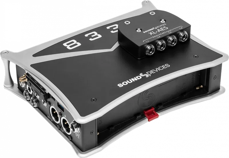
    enter image description here

    Practical Setup & Configuration

    • Menu Navigation: You must enable the XL-AES in the System Menu before it appears as a source. Otherwise, the 833 is expecting an analog signal. Here's a two minute explainer. (YouTube)

    • Routing: The 833’s fully routable architecture can easily map inputs to tracks. Once the input is enabled, you simply go to your desired channel, open the Source menu, and select the digital source (e.g., "AES 1" or the corresponding XL-AES channel).

    • Sample Rate Sync: When using digital inputs, the 833 becomes the "clock master" (or the source must be synced), though the 833's internal converters handle this automatically when set up correctly.

    Critical Best Practices

    • Cable Matters: It's not difficult to emphasize the importance of using 110-ohm impedance AES cables. While a standard analog mic cable might "work" over short distances, using proper AES-rated cabling is essential to prevent data errors, dropouts, or "clicks and pops" in the recording. (Soundrolling) More on this in a bit...

    • AES42 vs. AES3: AES42 is for specific digital microphones that require power, while AES3 is the standard for transferring digital audio between devices. (see a recent post for more)

    • Gain Staging: Note, you still have digital trim control. You aren't adjusting an analog preamp, but you are adjusting the signal level within the digital domain!

    Key Technical Specs

    Feature Detail
    Connector (Standard) XLR-3 (Input 1)
    Connector (Expansion) TA3 (via XL-AES accessory)
    Cable Requirement 110-ohm balanced
    Protocol AES3 (2-channel)
    833 Flexibility Fully routable to any track

    More on Cables

    The Core Requirement: 110-Ohm Impedance

    The most important technical rule is that AES3 signals require 110-ohm shielded twisted-pair cable. (Reddit)

    • Why it matters: Analog microphone cables typically have an impedance between 50 and 75 ohms. While they might pass a signal over a very short distance (like 1 meter), they cause "reflections" of the digital data stream. Over longer runs, this leads to bit errors, digital dropouts, and audible clicking or popping.

    • The "Pro" Habit: Because AES cables look identical to analog cables, it is common industry practice to label your digital cables. Use specific colors of electrical tape or colored heat-shrink tubing on the connectors to distinguish them at a glance during a high-pressure setup.

    Connector Types for the 833

    Depending on how you are connecting your devices, you will encounter two primary connector types:

    • XLR-3 (Input 1): If you are using the single digital input on the main chassis (Input 1), you need a standard XLR-F to XLR-M cable rated for 110-ohm AES digital audio.

    • TA3 (XL-AES Accessory): If you are using the XL-AES expansion accessory, you will need TA3-F to XLR-M (or TA3-F to TA3-M, depending on your receiver) cables. These must also be wired using 110-ohm digital-rated cable.

    Best Practices: Ensuring a Bulletproof AES Workflow

    Transitioning to an all-digital signal chain is one of the most effective ways to lower your noise floor and simplify your gain structure. However, AES requires a shift in mindset compared to analog workflows. Follow these best practices to ensure your digital path remains as clean and reliable as the manufacturers intended.

    1. Identify Your Digital Lines

    Because AES cables look exactly like standard microphone cables, it is dangerously easy to mix them up in a dark bag or a busy sound cart. Establish a clear cable labeling system immediately. Whether you use colored heat-shrink, specific electrical tape, or entirely different brands of connectors, you should be able to identify a digital cable by touch or a quick glance. Never rely on "guessing" during a high-pressure setup.

    Respect the 110-Ohm Standard

    Do not use standard analog microphone cable for AES signals, even for short runs. While it may appear to work during a "bench test," analog cable lacks the specific impedance characteristics required to maintain data integrity. Using non-rated cable is an invitation for digital errors—resulting in intermittent dropouts, clicks, and pops that are notoriously difficult to track down once the cameras are rolling. Always use certified 110-ohm AES/EBU cable.

    Master Your Gain Staging

    When you move to AES, you are bypassing the analog preamp stage of the 833. This means your gain staging happens in the digital domain.

    • Understand the Signal Source: You are now controlling the gain of the transmitter or the preamp feeding the recorder, not the 833 itself.

    • Watch Your Levels: Because there is no analog saturation to "soften" a digital clip, keep a close eye on your peaks. Digital clipping is immediate and harsh. If your source level is too hot, adjust it at the receiver or the digital output stage of your source device, rather than trying to fix it at the recorder.

    Manage Your Clocking

    The 833 is highly capable of handling digital signals, but you must ensure your system is synchronized. In most single-recorder setups, the 833 will act as the master clock. If you notice any rhythmic "ticking" or artifacts in your signal, verify that all devices in your digital chain are synced to the same sample rate (e.g., 48kHz or 96kHz). A mismatch in sample rates is a frequent cause of digital noise.

    The "Listen-Test" Ritual

    Before calling "Speed" or "Action," perform a quick digital check. Because AES errors are binary—either the data arrives perfectly or it arrives with errors—you won't necessarily hear "hiss" if something is wrong. You will hear digital artifacts or silence. Use your headphones to specifically monitor the digital returns periodically, especially if you are using long cable runs or complex cabling looms.

    👉 Return to RR.COM 👈

  • Posted on
    Digital Integrity: Understanding AES3 and AES42 for Film & Television

    Digital Integrity: Understanding AES3 and AES42 for Film & Television

    In the modern production ecosystem, the transition from analog signal chains to pure digital workflows has been essential for maintaining fidelity from the sound stage to the final mix. Among the critical standards facilitating this are AES3 and its sophisticated sibling, AES42. (Nassau National Cable)

    For technical directors, sound recordists, and post-production engineers, understanding these protocols is not just academic—it is vital for troubleshooting, hardware integration, and maintaining absolute signal integrity.

    AES3: The Backbone of Digital Interconnects

    Often referred to by its older moniker, AES/EBU, AES3 is the professional standard for transmitting two channels of linearly represented digital audio (LPCM) over a single cable.

    Technical Foundations

    • Physical Layer: Typically carried over 110Ω balanced shielded twisted-pair cable with XLR connectors. An "AES3-id" variant also exists, utilizing 75Ω coaxial cable and BNC connectors, which is often preferred for long cable runs due to lower susceptibility to interference. (Dutch & Dutch)

    • Data Structure: Each AES3 "block" consists of 192 frames. Each frame contains two subframes (Channels A and B), providing enough bandwidth for audio resolutions up to 24-bit/192kHz. (Library of Congress)

    • Synchronization: AES3 carries the clock embedded within the data stream. However, in complex multi-device environments (like a large film set), relying solely on embedded clocking can lead to jitter or sync issues. It is standard practice to clock all digital devices to a central master word clock. (Sharada Audio)

    AES42: The Digital Microphone Frontier

    If AES3 is the highway for digital audio, AES42 is the intelligent vehicle designed to ride it. It is the international standard for microphones with a digital output. (Black Level AV)

    Why AES42 Matters

    By digitizing the signal at the capsule—before it ever hits a long cable run—AES42 eliminates the degradation and noise pickup associated with analog microphone-level signals.

    Key Features

    • Digital Phantom Power (DPP): Unlike analog phantom power (48V), AES42 provides 10V of power that also acts as a carrier for control data. (Sound On Sound)

    • Remote Control: A standout feature of AES42 is the ability for the receiving device (a mixer or recorder) to control the microphone’s internal settings, such as gain, polar patterns, low-cut filters, and limiters. (DiGiCo)

    • Operational Modes:

      • Mode 1: Simple "plug-and-play." The microphone provides an output, but the receiver cannot control its internal parameters.

      • Mode 2: Full bidirectional communication. This allows for remote control of the microphone's processing parameters and requires synchronization between the mic and the receiver.

    Comparison at a Glance

    Feature AES3 (AES/EBU) AES42
    Channel Count 2 channels per stream 1 or 2 channels per stream
    Power No power (signal only) 10V Digital Phantom Power (DPP)
    Control None (data stream only) Remote control of mic parameters (Mode 2)
    Physical XLR (110Ω) or BNC (75Ω) Standard XLR (specialized wiring)
    Primary Use Interconnect between equipment (mixers, recorders, converters) Direct connection for digital microphones

    Implementation in Modern Workflows

    For the film and television industry, the choice between these protocols usually comes down to signal path purity.

    1. Eliminating Gain Stages: AES42 allows the signal chain to remain digital from the diaphragm to the recording medium. By removing the analog preamp stage, you eliminate the noise floor and harmonic distortion inherent in analog amplification. (nuprime-x)

    2. Cable Management: In environments with heavy RF interference, such as large stage sets or urban locations, moving to digital transmission via AES3-id (coax) or AES42 provides significantly better immunity than standard balanced analog microphone cables.

    3. Synchronization Requirements: When deploying AES42, always ensure your hardware supports the required Mode (1 or 2). Mis-matching a Mode 2 microphone with a non-compliant receiver can lead to complete signal failure or, at minimum, a loss of the remote-control functionality that makes the standard so powerful.

    As production workflows continue to demand higher channel counts and uncompromising clarity, these standards remain the foundation upon which professional audio reliability is built. Understanding the nuances of how these bits traverse your signal path is the first step toward mastering the modern digital sound stage.

    👉 Return to RR.COM 👈